


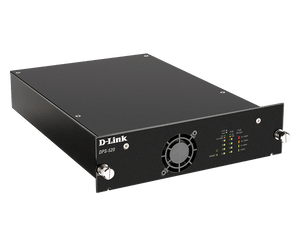
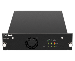
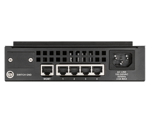
D-Link DPS-520 180 W PoH Redundant Power Supply
A Separate Power Path for Supported Network Switches The DPS-520 provides a shared 180 W redundant-power budget for supported non-PoE D-Link DGS-1520-28 and DGS-1520-52 switches. Four PoH outputs can provide a second power path for up to four compatible hosts through suitable Ethernet cabling. Its separate management interface supports status monitoring and port-priority settings. This is a model-specific redundant-power system rather than a general-purpose IEEE 802.3af/at camera or access-point injector, and it does not contain a backup battery. Highlights Power Redundancy 180 W total shared output budget. Up to 90 W per output; shared budget still applies. Four PoH outputs for supported non-PoE DGS-1520 hosts. Installation Standard CAT5e or suitable better cable, up to 100 m per supported connection. Standalone use or optional DPS-800 rack chassis. 90–264 V AC input. Administration Separate Gigabit management connection. Web status reporting and output-priority control. 1-year warranty. Key Features Give a Compatible Switch a Second Power Path An internal switch power-supply fault can disconnect every device behind the switch. The DPS-520 adds a supported redundant-power path to non-PoE DGS-1520-28 and DGS-1520-52 switches. Compatibility is model-specific; a familiar Ethernet connector does not make an arbitrary switch or PoE endpoint suitable. Allocate the Shared Power Budget The four outputs share a total 180 W budget, with up to 90 W available from an individual output within that total. Four outputs do not mean four simultaneous 90 W loads. Size the complete installation and its priority settings for the intended hosts and failure conditions. Use the Supported PoH Connection Power over HDBaseT connections allow a compatible switch to receive its redundant power over standard CAT5e cabling at distances up to 100 m. Follow the host and supply instructions for the connection. Do not treat the output as an ordinary 802.3af/at injector for cameras, phones or access points. Monitor the Redundant Supply A dedicated management interface separates administration from the four power outputs. Web status reporting and output priorities help the administrator understand the connected power arrangement. Protect access to this interface and test the intended failover behaviour before relying on the system. Fit the Equipment Layout Use the supply as a standalone unit or mount suitable modules in the optional DPS-800 two-slot rack chassis. Allow clearance for ventilation, cable routing and service access. The chassis is a separate accessory; a redundant-power installation should be planned with the supported host and all required connection cables. Separate Redundancy From Battery Runtime The DPS-520 uses AC mains and contains no backup battery. It helps address a supported switch’s internal supply failure, but cannot provide runtime when all AC sources fail. Use a suitable UPS and a tested power arrangement if mains-outage continuity is required. Summary The DPS-520 is a dedicated redundant-power option for supported non-PoE DGS-1520 switches. Its four outputs, shared budget and management functions support a deliberate availability design when the host models, cabling, power priorities and separate UPS requirements are checked together. Frequently Asked Questions Which Switches Does It Support?ExpandCollapse The verified application is the non-PoE DGS-1520-28 and DGS-1520-52. Check the exact hardware and required connection arrangement before ordering. It is not a universal redundant supply for every D-Link switch. Can It Power a Camera or Access Point?ExpandCollapse Do not use it as a general 802.3af/at camera or AP injector. Its PoH redundant-power outputs are for the specifically supported switch application. Can Every Port Deliver 90 W at Once?ExpandCollapse No. The maximum per output is 90 W, while the complete unit shares a 180 W total budget. Plan the combined load and output priorities. How Far Can the Connection Run?ExpandCollapse Up to 100 m using suitable CAT5e or better cabling in the supported host arrangement. Follow the installation requirements for the complete link. Is It a Battery UPS?ExpandCollapse No. It requires AC mains and has no battery runtime. An appropriate UPS is separate if the installation must keep operating during a loss of mains power. Is the Rack Chassis Included?ExpandCollapse No. The optional DPS-800 two-slot rack chassis is separate. The DPS-520 can also be used as a standalone power-supply unit.
Maaaring kunin sa 3005, Ubi Avenue 3, #01-88
Usually ready in 2-4 Business Day (Excluding Public Holiday)
D-Link DPS-520 180 W PoH Redundant Power Supply
Paglalarawan
A Separate Power Path for Supported Network Switches
The DPS-520 provides a shared 180 W redundant-power budget for supported non-PoE D-Link DGS-1520-28 and DGS-1520-52 switches. Four PoH outputs can provide a second power path for up to four compatible hosts through suitable Ethernet cabling.
Its separate management interface supports status monitoring and port-priority settings. This is a model-specific redundant-power system rather than a general-purpose IEEE 802.3af/at camera or access-point injector, and it does not contain a backup battery.
Highlights
Power Redundancy
- 180 W total shared output budget.
- Up to 90 W per output; shared budget still applies.
- Four PoH outputs for supported non-PoE DGS-1520 hosts.
Installation
- Standard CAT5e or suitable better cable, up to 100 m per supported connection.
- Standalone use or optional DPS-800 rack chassis.
- 90–264 V AC input.
Administration
- Separate Gigabit management connection.
- Web status reporting and output-priority control.
- 1-year warranty.
Key Features
Give a Compatible Switch a Second Power Path
An internal switch power-supply fault can disconnect every device behind the switch. The DPS-520 adds a supported redundant-power path to non-PoE DGS-1520-28 and DGS-1520-52 switches. Compatibility is model-specific; a familiar Ethernet connector does not make an arbitrary switch or PoE endpoint suitable.
Allocate the Shared Power Budget
The four outputs share a total 180 W budget, with up to 90 W available from an individual output within that total. Four outputs do not mean four simultaneous 90 W loads. Size the complete installation and its priority settings for the intended hosts and failure conditions.
Use the Supported PoH Connection
Power over HDBaseT connections allow a compatible switch to receive its redundant power over standard CAT5e cabling at distances up to 100 m. Follow the host and supply instructions for the connection. Do not treat the output as an ordinary 802.3af/at injector for cameras, phones or access points.
Monitor the Redundant Supply
A dedicated management interface separates administration from the four power outputs. Web status reporting and output priorities help the administrator understand the connected power arrangement. Protect access to this interface and test the intended failover behaviour before relying on the system.
Fit the Equipment Layout
Use the supply as a standalone unit or mount suitable modules in the optional DPS-800 two-slot rack chassis. Allow clearance for ventilation, cable routing and service access. The chassis is a separate accessory; a redundant-power installation should be planned with the supported host and all required connection cables.
Separate Redundancy From Battery Runtime
The DPS-520 uses AC mains and contains no backup battery. It helps address a supported switch’s internal supply failure, but cannot provide runtime when all AC sources fail. Use a suitable UPS and a tested power arrangement if mains-outage continuity is required.
Summary
The DPS-520 is a dedicated redundant-power option for supported non-PoE DGS-1520 switches. Its four outputs, shared budget and management functions support a deliberate availability design when the host models, cabling, power priorities and separate UPS requirements are checked together.
Frequently Asked Questions
Which Switches Does It Support?
The verified application is the non-PoE DGS-1520-28 and DGS-1520-52. Check the exact hardware and required connection arrangement before ordering. It is not a universal redundant supply for every D-Link switch.
Can It Power a Camera or Access Point?
Do not use it as a general 802.3af/at camera or AP injector. Its PoH redundant-power outputs are for the specifically supported switch application.
Can Every Port Deliver 90 W at Once?
No. The maximum per output is 90 W, while the complete unit shares a 180 W total budget. Plan the combined load and output priorities.
How Far Can the Connection Run?
Up to 100 m using suitable CAT5e or better cabling in the supported host arrangement. Follow the installation requirements for the complete link.
Is It a Battery UPS?
No. It requires AC mains and has no battery runtime. An appropriate UPS is separate if the installation must keep operating during a loss of mains power.
Is the Rack Chassis Included?
No. The optional DPS-800 two-slot rack chassis is separate. The DPS-520 can also be used as a standalone power-supply unit.
Mga detalye
D-Link DPS-520 180 W PoH Redundant Power Supply
The DPS-520 is a PoH redundant power supply for supported non-PoE DGS-1520-28 and DGS-1520-52 switches. Four power outputs share a 180 W total budget, with a 90 W per-output limit within that total. A separate Gigabit management interface supports web status reporting and priority settings. Use suitable CAT5e or better cabling in the supported host arrangement. The unit can operate separately or in an optional DPS-800 chassis. It is mains-powered, has no battery and is not a general-purpose camera or access-point PoE injector.
| Specification | Details |
|---|---|
| Purpose and Compatibility | |
| Supported Hosts | Non-PoE DGS-1520-28 and DGS-1520-52; verify exact hardware/connection requirements |
| Output Technology | PoH redundant-power application; not a generic IEEE 802.3af/at endpoint injector |
| Power Outputs | 4 × 10/100/1000BASE-T PoH connections |
| Management | 1 × 10/100/1000BASE-T management connection; web status/priority control |
| Electrical and Cabling | |
| Total Output Budget | 180 W shared |
| Per-Output Limit | Up to 90 W within the shared total |
| AC Input | 90–264 V AC, 47–63 Hz |
| Connection Cabling | Suitable CAT5e or better; up to 100 m in the supported arrangement |
| Battery | None; UPS purchased separately |
| Physical and Environmental | |
| Mounting | Standalone or optional DPS-800 two-slot rack chassis |
| Dimensions | 196 × 257 × 52 mm |
| Device Weight | 1.15 kg |
| Operating Temperature | 0°C to 50°C |
| Storage Temperature | −40°C to 70°C |
| Humidity | Operating 10–90%; storage 5–95% RH |
| Warranty | 1 year |
| Installation Requirements | |
| Required Separately | Compatible switches, suitable cabling and any optional rack chassis/UPS |
| Commissioning | Confirm combined power load, output priorities and failover operation |